Arduino Workshop First Edition Errata
Page 6:
Two suppliers to add to the list are:
Altronics (http://www.altronics.com.au)
Jaycar (http://www.jaycar.com.au)
Page 13:
The first sentence on the page should read, "Copy the folder named arduino-1.0.5-windows (or something similar)..."
Page 27:
The first sentence on the page should read, "At the bottom right of the message area, you should see the name of your Arduino board type as well as its connected USB port- Arduino Uno on COM4 in this case."
Page 67:
The text for section 3 should read, “Connect one wire from the Arduino 5 V pin to the leftmost vertical column on the breadboard, and connect another wire from the Arduino GND pin to the vertical row to the right of the 5 V column, and another horizontal wire between the vertical GND column and the bottom-left pin of the button, as shown in Figure 4-22.”
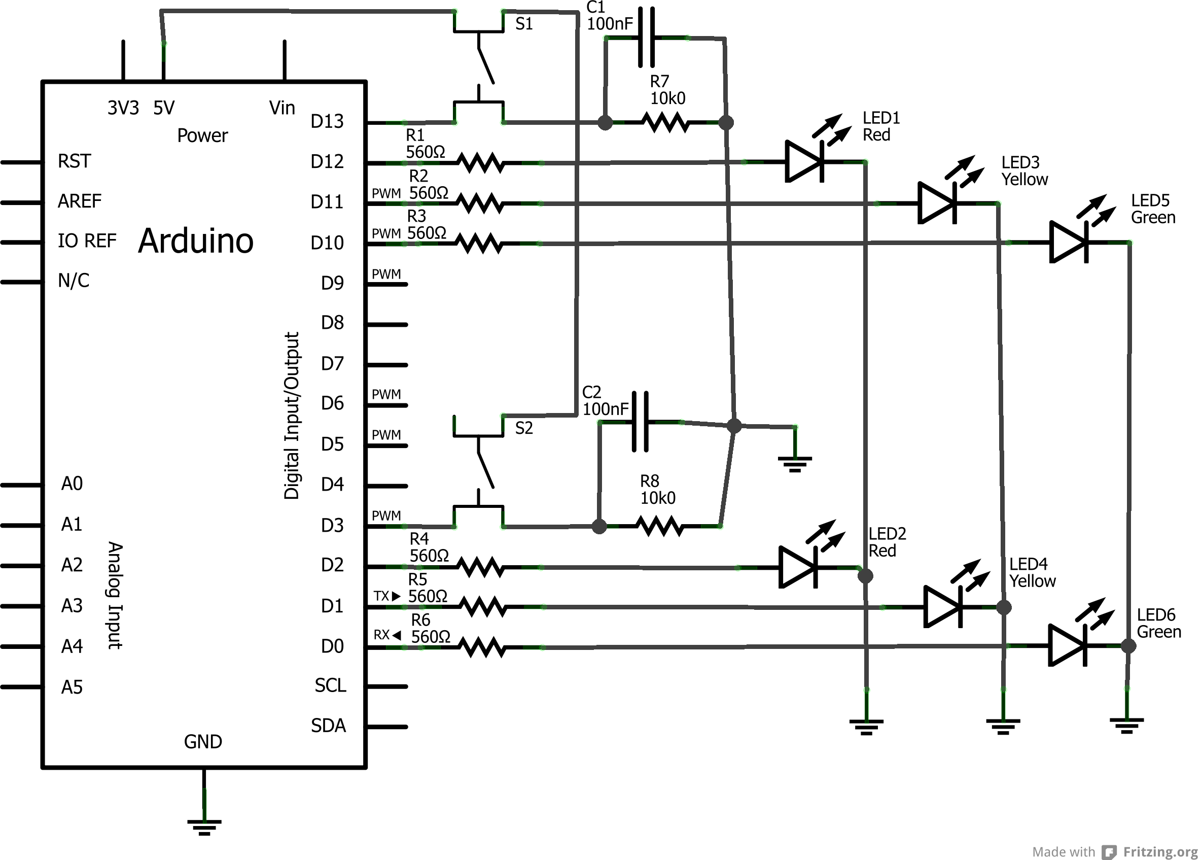
Page 75:
In Figure 4-26, there should be a ground connection on the line that connects R7 with R8. Please see the following image for the correct figure:
Page 76:
In the sketch for Project 5, the first line of code which reads "#define westButton 7" should instead read "#define westButton 3".
Page 85:
In the formula in the middle of the page, "R3" should instead read "R2".
Page 87:
At the bottom of the page, the text that reads "When alternating current is applied..." should instead read “When a pulsed current is applied..."
Page 121:
In the block of code at the top of the page, the line which reads "shiftOut(DATA, CLOCK, MSBFIRST, a);" should instead read "shiftOut(DATA, CLOCK, MSBFIRST, i);"
Page 133:
The bolded segment in the following text should be added to the sketch for program 19:
// Project 19 - Controlling Two Seven-Segment LED Display Modules

// set up the array with the segments for 0 to 9, A to F (from Table 6-2)
#define DATA 6 // connect to pin 14 on the 74HC595
#define LATCH 8 // connect to pin 12 on the 74HC595
#define CLOCK 10 // connect to pin 11 on the 74HC595
void setup()
{
pinMode(LATCH, OUTPUT);
pinMode(CLOCK, OUTPUT);
pinMode(DATA, OUTPUT);
}
int digits[] = {
252, 96, 218, 242, 102, 182, 190, 224, 254, 246, 238, 62, 156, 122, 158, 142};
void displayNumber(int n)
{
int left, right=0;
if (n < 10)
{
digitalWrite(LATCH, LOW);
shiftOut(DATA, CLOCK, LSBFIRST, digits[n]);
shiftOut(DATA, CLOCK, LSBFIRST, 0);
digitalWrite(LATCH, HIGH);
}
else if (n >= 10)
{
right = n % 10; // remainder of dividing the number to display by 10
left = n / 10; // quotient of dividing the number to display by 10
digitalWrite(LATCH, LOW);
shiftOut(DATA, CLOCK, LSBFIRST, digits[right]);
shiftOut(DATA, CLOCK, LSBFIRST, digits[left]);
digitalWrite(LATCH, HIGH);
}
}
void loop()
{
int i;
for ( i = 0 ; i < 100 ; i++ )
{
displayNumber(i);
delay(100);
}
}
Page 135:
The description under the heading "LED Matrix Display Modules" should also include that this specific LED matrix module is a common-cathode display.
Page 145:
In Project 23, the lines of code which read:
shiftOut(DATA, CLOCK, MSBFIRST, ~smile[a]); // columns

shiftOut(DATA, CLOCK, MSBFIRST, binary[a]); // rows
Should instead read:
shiftOut(DATA, CLOCK, MSBFIRST, ~smile[i]); // columns

shiftOut(DATA, CLOCK, LSBFIRST, binary[i]); // rows
Page 153:
In the last line of the code of the sketch for Project 25, "lcd.write(0);" should instead read "lcd.write(byte(0));"
Page 192:
The first line of code on the page which reads "if (attempt[q]==PIN[q])" should instead read "if (attempt[i]==PIN[i])"
Page 210:
The heading that reads "Atmel ATmega328-PU Microcontroller IC" should instead read “Atmel ATmega328P-PU Microcontroller IC". The same change can be made for every instance of "ATmega328” or "ATmega328P” in this project, which should instead read "ATmega328P-PU".
Page 235:
The Pololu RP5 has been discontinued, however the Dagu Rover 5 is an ideal replacement - for example: http://www.pololu.com/catalog/product/1550"
Page 260:
In the block of code for Listing 13-1, the line which reads "byte a" should instead read "byte a;"
Page 345:
Ignore the note which states that teleduino only works with an ATmega328 microcontroller. It now works on all microcontrollers.